blog 

Designing for Metal Injection Molding

Metal injection molding (MIM) is a technology that solves a lot of problems that are not being solved for today. At OptiMIM, we use the injection molding process to create net-shaped parts that are ideal for high performance, high density, high strength, and high corrosion resistance applications that lead the industry in mechanical and physical properties. When designing for MIM there are several considerations that need to be discussed in order to develop a successful project. Keep reading to discover the unique variables that we design into our award-winning components.
MIM Molding Variables
When you design for metal injection molding you have to take a number of things into account. The mold could be a two-plate or three-plate design, but when you’re designing the part you have to consider where you will allow or not allow certain details or features—such as gating and the gate location. In some instances, we may have a single gate or multiple gates depending on the geometry of the part design.
Parting Lines
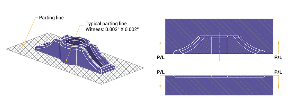
You also have to consider parting line and parting line witness. All parts have a parting line relative to being able to mold the component, but what we have to be mindful of your application and understanding whether or not the parting line on your geometry impacts the form, fit, or function of the part. In other words, we don’t want a parting line on a surface that may be functional.

Ejector Marks
The other thing that you have to be aware of is ejector marks. All parts have to be ejected from the mold, so we have to look at the ejector location relative to the function. In some cases, we may utilize a sleeve ejection that can minimize ejector marks altogether.
Wall Features & Wall Thickness
Other things we have to consider are thin wall features, particularly if you’re talking about 0.020” or less in wall thickness. When you’re injecting thin features in a mold there is a risk that if it’s not ejected properly those features could actually break off in a green state. These are all things that our engineers take in into consideration and we work with you in advance of developing a new program.

For the full list of molding variables, download our MIM Design webinar!
MIM Design Considerations
After we get past molding variables, we start looking at design considerations. And due to the complexity of the MIM process, there are quite a few design features that need to be addressed at each stage.
Drag Effect
During the sintering stage, there are two process variables that we have to consider. The first is drag effect which is merely the fact that inherent to the MIM process, a part shrinks on the tiles when they’re placed into our sintering ovens. Keep in mind from the MIM 101 webinar, that on average, a MIM part will shrink about 20 percent. Specific shrink rates depend on the grade of the material and our engineering team designs the part with shrinking factored in.

Sag Effect
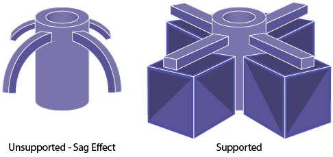
The second effect that occurs during the sintering process is the sag effect. During sintering, parts become relatively soft and because of gravity, cantilevered or unsupported features tend to want to run or sag. To design for the sag effect, we create a design that counters the effects of gravity. We can add special centers or ceramics that could be individual blocks, or custom machine ceramics to maintain those unsupported features.
Another option is working with you to modify your design to accommodate this goal without adding any additional costs. We look to add features like gussets on the part. Again, this would be ideal as long as it doesn’t affect your form, fit, or function of your application.

Draft Angles
The design characteristics for metal injection molding are very similar to plastic injection molding. However, the one main exception is the requirement of draft angles. In most cases for metal injection molding, we don’t require any draft angles at all. It’s a rare requirement.
The only time we might require a draft angle is if we have a high aspect ratio feature and we need to pull the mold, such as a thin wall section or a long core pin. We may introduce a half-a-degree draft just for additional relief, but for the most part, we don’t require a draft angle. The reason; we have a paraffin wax in the feedstock and that wax acts as a mold release agent so it allows us to have, for the most part, straight holes in the mold. There’s very little shrinkage that occurs at the molding stage. For that reason, it allows us to not require a draft angle.
Wall Thickness
Another thing about metal injection molding that’s very similar to that of plastic injection molding is uniform wall thickness. An ideal MIM part has similar wall thickness throughout so that we can control the shrinkage variability.
Undercuts
At OptiMIM, we create component designs with a collapsible core—a functionality in the mold that allows us to actually mold in undercuts so that we can reduce the need for a secondary operation and cost. Undercuts are typically impossible in some cases or challenging with other process technologies, but it is definitely doable with metal injection molding. Before designing for undercuts, we strongly recommend speaking with our engineering team for advice.

To learn more about mold and design variables for the metal injection molding process, I invite you to download our free webinar. We’ll discuss the above topics in more detail and cover more on:
- Knurling
- Custom feedstock
- Gating
- Secondary operations
- Solving functional or assembly issues
- And more!
OptiMIM works with many of the world’s most demanding manufacturers—from medical and defense to automotive and consumer electronics. They know we deliver the quality and performance they need to create better products, more consistently, whatever the volume. From the initial design stage all the way through to full production, let our team of experienced engineers help you drive your business forward—contact us today!


